The Electromagnetic Interference of LED Power Supply is not a Problem
2022-02-11 09:19:11
Friends familiar with power circuit design know that in the design process of
LED power supply, electromagnetic interference EMI is not a small problem, so how to solve this problem? This article will share the treatment of electromagnetic compatibility from this perspective, so that electromagnetic interference is no longer a problem!
Electromagnetic compatibility (EMC) is the study in electricity of the generation, propagation and reception of unexpected electromagnetic energy, and the harmful effects caused by such energy. The goal of electromagnetic compatibility is the ability of different equipment involved in electromagnetic phenomena to operate normally in the same environment without causing intolerable electromagnetic interference to any equipment in the environment. Traditionally, EMC includes two aspects: EMI (electromagnetic interference) and EMS (electromagnetic sensitivity).
Electromagnetic interference (EMI) refers to any electromagnetic phenomenon caused by conduction or electromagnetic field accompanied by voltage or current that can degrade the performance of a device, equipment or system or cause adverse effects.
LED power EMI, engineers should consider the main aspects: circuit measures, EMI filtering, component selection, shielding and printed circuit board anti-interference design, etc. First, several factors affecting EMC
(1) The circuit structure of the driving power supply
The original LED power supply was linear power supply, but linear power supply lost a lot of energy in the form of heat when operating. Linear power supply working mode, so that he from high voltage to low voltage must have a voltage device, generally are transformers, and then through rectification output DC voltage. Although bulky, heat, the advantage is that external interference is small, electromagnetic interference is small, but also easy to solve.
And now use more LED switching power supply, are IN the form of PWM LED drive power supply is to let the power transistor work in on and off state. On, low voltage, high current; When switching off, the voltage is high and the current is small, so the loss generated on the power semiconductor device is also very small. The disadvantage is more obvious, electromagnetic interference (EMI) is more serious.
(2) Switching frequency
The electromagnetic compatibility of LED power supply is generally the switching circuit in the power supply. The switching circuit is one of the main interference sources of switching power supply.
The switching circuit is the core of LED drive power supply. The switching circuit is mainly composed of switching tube and high frequency transformer. The DU/DT generated by it has larger pulse, wider frequency band and rich harmonics.
The main reason for this high frequency pulse interference is that the switch tube is loaded with the primary coil of high frequency transformer and is a inductive load. Switch pulse spike
Figure 1: Generation of switching pulse spikes
At the moment of conduction, the primary coil produces a large inrush current and a high surge peak voltage appears at both ends of the primary coil; At the moment of disconnection, due to the flux leakage of the primary coil, part of the energy is not transmitted from the primary coil to the secondary coil, and a attenuated oscillation with a peak is formed in the circuit, which is superplaced on the turn-off voltage to form a turn-off voltage spike.
High-frequency pulses produce more emissions, and periodic signals produce more emissions. In an LED power supply system, a current spike is generated by the switching circuit, which also generates a current spike when the load current changes. This is one of the sources of electromagnetic interference.
(3) the ground
Of all EMC problems, the main one is caused by improper grounding. There are three methods of signal grounding: single point, multipoint and mixed. When the switching circuit frequency is lower than 1MHz, single point grounding method can be adopted, but it is not suitable for high frequency; In high frequency applications, multipoint grounding is preferred. Mixed grounding is a method of single point grounding for low frequency and multi-point grounding for high frequency. Ground layout is key. Ground circuit of high frequency digital circuit and low level analog circuit should not be mixed.
(4) PCB design
Proper printed circuit board (PCB) wiring is critical to prevent EMI.
(5) Reset circuit design of intelligent LED power supply
In LED power supply, there are a number of intelligent LED power supply controlled by single chip microcomputer, and some LED power supply by single chip microcomputer control the duty ratio of switch circuit, the watchdog of the single chip microcomputer system for the whole run of LED power supply plays an important role in particular, because all of the interference sources cannot all be isolated or to, once in the CPU interfere with the normal operation of the program, The combination of a reset system and software processing is an effective error-correction defense. There are two common reset systems:
① External reset system. External watchdog circuits can be designed in-house or built with dedicated Watchdog chips. Thus, if the program system is stuck in an infinite loop, and the loop happens to have a "feed the dog" signal, the reset circuit will not be able to perform its intended function.
(2) there are more and more LED power supply with its own on a chip reset system, so users can easily use its internal reset timer, however, some smart LED power supply control circuit reset instruction is too simple, that will also exist such as the infinite loop "dog" instruction, make its loss to the monitoring role.
Second, the hardware processing method of interference measures
To solve the electromagnetic interference problem of LED drive power supply, we can start from the following aspects:
1. Reduce the interference of switching power supply itself
(1) soft switching technology: in the original hard switching circuit to increase inductance and capacitance components, the use of inductance and capacitance resonance, reduce the switching process DU/DT and DI/DT, so that the switching device when the voltage drop before the current rise, or off the current drop before the voltage rise, to eliminate the overlap of voltage and current.
② Switching frequency modulation technology: by modulating switching frequency FC, focus on FC and its harmonics 2FC, 3FC... In order to reduce the EMI amplitude at each frequency point.
③ Selection of components: select components that are not easy to produce noise, conduction and radiation noise. Special attention is usually paid to the selection of winding components such as diodes and transformers. The fast recovery diode with low reverse recovery current and short recovery time is an ideal device for high frequency rectification of switching power supply.
④ Reasonable use of electromagnetic interference filter: one of the main purposes of EMI filter, power grid noise is a kind of electromagnetic interference, it belongs to radio frequency interference (RFI), its transmitted noise spectrum is roughly 10KHz~30MHz, up to 150MHz.
In general, differential mode interference is small in amplitude and frequency, resulting in small interference; Common mode interference amplitude, high frequency, but also through the wire radiation, resulting in greater interference. In order to weaken the conducted interference, the most effective method is to install emi filters in the input and output circuits of switching power supply.
LED power supply generally adopts simple single-stage EMI filter, mainly including common mode choke and filter capacitor.
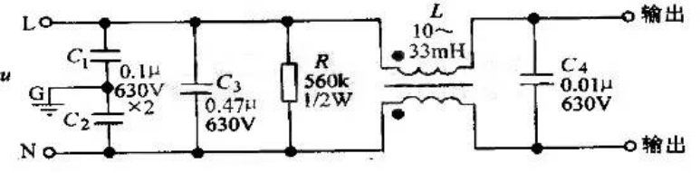
Figure 2 shows commonly used LED power filters. L, C1 and C2 are used to filter common mode interference, while C3 and C4 filter series mode interference. When common-mode interference occurs, the two coils in L have the same magnetic flux direction, and the total inductance increases rapidly after coupling, so the common-mode signal shows a great inductive reactance, making it difficult to pass through, so it is called common-mode choke. Its two coils are wound around ferrite rings with low loss and high permeability. R is the discharge resistance, which can discharge the accumulated charge on C3, so as to avoid affecting the filtering characteristics due to the accumulation of charge. After power failure, it can also make the incoming end L and N of the power supply not charged, so as to ensure the safety of use.
Figure 2: Commonly used LED power filter
⑤EMI filter can effectively suppress the electromagnetic interference of switching power adapter
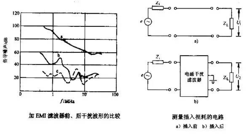
In Figure 3, curve A is the waveform of conduction noise from 0.15mhz to 30MHz on the SWITCHING power adapter without EMI filter.
Curve B is the waveform after adding EMI filter, which can attenuate electromagnetic interference by 50 dB (Uv)~70 dB (Uv). Obviously, insertion of EMI filter results in better results. The noise voltage transmitted to the load before and after adding the emi filter is set as U1 and U2 respectively, and the calculation formula is 20lgU1/U2.
The insertion loss is expressed by decibel dB. The higher the decibel value is, the stronger the ability to suppress noise interference is.
The circuit for measuring insertion loss is shown in Figure 3. E is the noise signal generator, Zi is the internal impedance of the signal source, and ZL is the load impedance, generally 50 ohms. The noise frequency ranges from 10KHz to 30MHz. Firstly, the noise pressure drops U1 and U2 at both ends of the load before and after adding EMI filter are measured at different frequencies. Then, the insertion loss value at each frequency point is calculated by substituting the formula 20lgU1/U2. Finally, the insertion loss curve is summarized.
Figure 3: Before and after adding EMI filter
2. Cut off the transmission path of interference signals;
① Interference from power line can be filtered out by power line filter. A reasonable and effective EMI filter for switching power supply should have a strong suppression effect on the differential mode and common mode interference on the power line.
② Improve the electromagnetic compatibility design of PCB board
PCB is the support of circuit components and devices in LED power supply system. It provides the electrical connection between circuit components and devices. With the rapid development of electronic technology, PCB density is getting higher and higher. The design of PCB has great influence on the electromagnetic compatibility of LED power supply system.
Practice has proved that even if the circuit schematic design is correct and the printed circuit board design is improper, the reliability of LED power supply system will be adversely affected.
PCB anti-interference design mainly includes PCB layout, wiring and grounding, its purpose is to reduce the electromagnetic radiation of PCB and the crosstalk between circuits on PCB.
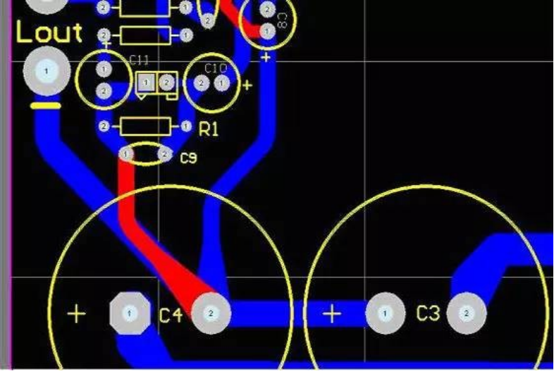
Figure 4: Proper selection selects the main filter capacitor pin as the centralized ground point
In addition, the frequency of ac sound caused by electromagnetic interference of transformers is generally about 50HZ, while the ac sound caused by improper grounding wiring is about 100HZ due to the frequency doubling of the rectifier circuit, which can be detected by careful differentiation.
The correct wiring method is shown in Figure 4. The main filter capacitor pin is selected as the centralized grounding point, and the strong and weak signal ground wires are strictly separated and summarized at the general grounding point.
Therefore, when designing printed circuit board, we should pay attention to the correct method, comply with the general principle of PCB design, and should meet the design requirements of anti-interference.
3. Enhance the anti-jamming ability of the interfered body.
In the LED power supply system, the input/output is also the conduction line of the interference source, and the pick up source of the radio frequency interference signal, we generally take effective measures when designing:
(1) The necessary common mode/differential mode suppression circuit should be adopted, and certain filtering and anti-electromagnetic shielding measures should be taken to reduce the interference advance.
(2) As far as possible to take all kinds of isolation measures (such as photoelectric isolation or magnetoelectric isolation), so as to block the propagation of interference.
(3) Lightning protection measures
The LED power supply system used outdoors or the power line and signal line introduced indoors should be considered for lightning protection. Common lightning protection devices are: gas discharge tube, TVS (TransientVoltageSuppression), etc. Gas discharge tube is when the voltage of the power supply is greater than a certain value, usually tens of V or hundreds of V, gas breakdown and discharge, the strong impact pulse on the power line into the earth. TVS can be regarded as two parallel Zener diodes in opposite directions, which turn on when the voltage at both ends is higher than a certain value. It is characterized by transient currents of hundreds or thousands of A.
Therefore, LED power electromagnetic electromagnetic interference control technology mainly includes: circuit measures, EMI filtering, component selection, shielding and printed circuit board anti-interference design. Can solve these problems correctly and reasonably, through the LED drive power supply successfully through the 3C certification, is not a problem!