What is the Crowbar Driver Circuit?
2022-02-14 13:58:31
Crowbar driver circuit
Crowbar circuit is an overvoltage protection circuit. The design idea of this circuit is to short-circuit the
power supply when the voltage exceeds a predetermined value, and hard the voltage of the power supply through short-circuit
Student's pull down. At this time, the over-current protection equipment such as the fuse on the power supply path works to cut off the power supply to prevent damage to the power supply. This mechanism tells us that the circuit is going to
The power supply can withstand a short short circuit without damage, otherwise although the protection of back-end equipment but at the expense of the power supply equipment.
Crowbar is a Crowbar, and the first thing I thought of when I first saw the word was a lever, thinking that this circuit was using some kind of lever principle. But then I found this electricity
The name of the road has nothing to do with leverage. A Crowbar circuit is essentially a Crowbar (or other thick, conductive stick) thrown into a power lead
Short circuit it out. That's an uncultured name!
Components such as thyristors are commonly used in Crowbar circuits. The device is not normally turned on, but can pass through a voltage or current at the control terminal
The signal turns it on. When the thyristor is turned on, the conduction pressure drop is about 1-2V. Crowbar circuits generally do not short-circuit the power supply with triodes or feTs, because when the power supply
Shorted, it cannot provide the base current needed to keep the transistor on. The SCR does not need to control the signal once it is turned on.
Basic Crowbar driver circuit
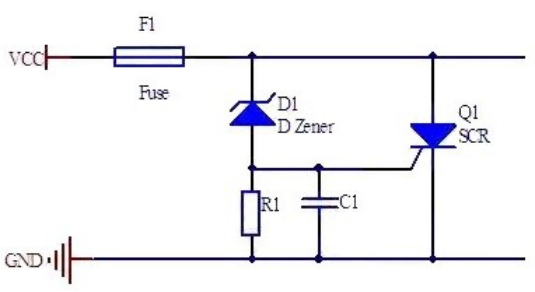
The diagram below shows a typical Crowbar circuit.
When the supply voltage exceeds the voltage regulator of the diode, D1 turns on. When the supply voltage exceeds the voltage regulator diode plus the thyristor on voltage, the thyristor on
Start, and lower the supply voltage to 1-2V. The SCR does not turn off until the current flowing through it decreases to near zero. Capacitors in a circuit are used to ensure that interference does not misstart
Move.
If the power supply's ability to output current is unlimited, soon the Crowbar circuit will burn out, so the power supply's output current must be limited, the easiest way to do this is to install a protection
The fuse or power supply itself is of the current limiting type.
A disadvantage of this circuit is that it is difficult to accurately control the opening voltage, after all, there are only a fixed number of regulated voltage diodes, and the discrete comparison of regulated voltage diodes
Large (2-5 %), also affected by temperature. SCR open voltage dispersion is also quite large. Therefore, when the power supply voltage is relatively low, we need to improve the above circuit to make it control
The voltage is more accurate.
Precise Crowbar driver circuit
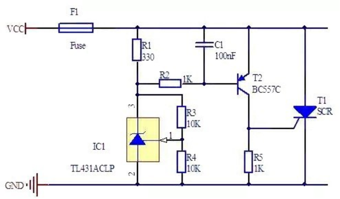
The opening voltage of the following circuit is much more accurate.
The 1TL431 is an inexpensive voltage source chip that can output between 2.5 and 36V. It can solve the problem of discreteness and voltage stability of regulated diode
It's also much better than a regulated diode.
Triode T2 is used to solve the problem of large discrete starting voltage of SCR. When Vbe is greater than 0.6V, the triode turns on the SCR. Due to the amplification of the triode
Small changes in source voltage can produce large voltage changes at the SCR control terminal. Although the triode is also affected by temperature, the entire circuit is more stable than the original opening voltage
The circuit is much smaller.
The TL431's reference voltage is 2.5V, so the output voltage of the TL431 in the above circuit is 5V, and the Crowbar circuit has an on voltage between 5.6-6.0V. This circuit can
Di/dt protection
There is still some room for improvement in the circuit above. When the inflow current at the control end of the SCR is only a little higher than the trigger opening current, the inside of the thyristor starts with only one
Part of the thyristor is open, and it will take some time for the thyristor to fully open. During this time a large amount of current passes through parts of the thyristor, which can easily damage the thyristor
Tube. There is an indicator in the thyristor chip manual called maximum DI/DT, and the thyristor is safe only when the rate of change of the current flowing through the thyristor is less than the maximum specified by this indicator
All of the. Typically, A 12A thyristor has A maximum di/dt of 100 A/µs.
The power input of the load usually has a large capacitor, and when the Crowbar circuit is working, this large capacitor will pour a large amount of current into the thyristor. Especially large volume
The ceramic capacitor produces a considerable di/ DT pulse One way to protect the thyristor from high current shocks is to connect an inductor in series to limit the DI /dt. The required
The inductance of can be calculated as follows:
U= L*di/dt
L = U/(di/dt)
In the circuit above, the opening voltage is about 6V and the thyristor's on-voltage drop is about 1V, so U= 6V- 1V= 5V. Suppose the thyristor can withstand di/dt
100A/µs, the inductance should not be less than 50 nH. Also, make sure the inductor can withstand enough current to at least avoid blowing a fuse.
Another CROWbar circuit based on TL431
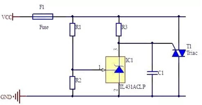
The TL431's chip manual gives a reference circuit as follows.
When the voltage at the TL431's reference input is below 2.5V, the current flowing through the TL431 does not exceed 400 µA, so the voltage drop across R3 is small. As the supply voltage increases the TL431
When the voltage at the reference input exceeds 2.5V, TL431 turns on, and the voltage drop on R3 increases until the thyristor turns on.
The operating voltage of this circuit is more accurate. But you have to use a bidirectional thyristor, ordinary unidirectional thyristors don't work.
Improved Crowbar circuit based on TL431
The above circuit can also be modified to further eliminate the effect of temperature on the thyristor.
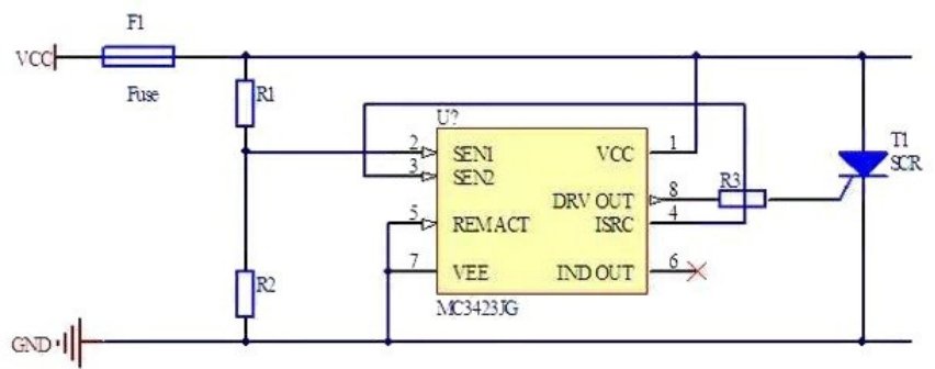
Crowbar controller
ON Semiconductor has a dedicated chip, THE MC3423, which controls the voltage more accurately and ensures that the thyristor quickly turns ON. Use a simple resistor voltage divider circuit
To set the opening voltage between 4.5V and 40V.
Compared with the previous circuit, this circuit has the disadvantage of higher power consumption and higher opening voltage