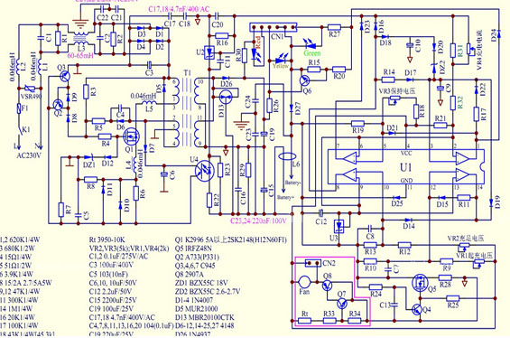
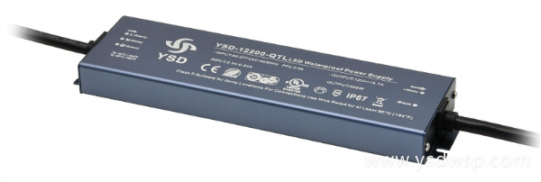
Detailed circuit diagram of switching power supply
2019-12-26 18:05:13
Believe that many readers do not know what is switching power supply, switching power supply is mainly used in industrial automation control, military industry equipment, industrial control equipment, communications equipment, power equipment, scientific research equipment, LED lighting, LCD, LED lamps and lanterns, communications equipment, etc can be used to, it is the use of modern power electronic technology, control switch tube opened and shut off time ratio, so as to maintain in the output voltage of a power supply. At present, switching power supply is widely used in the market with the characteristics of small size, light weight and high efficiency. It has made a great contribution to the rapid development of the electronic information industry. Today we are going to look at how switching power supply functions, to see the circuit diagram of switching power supply.

Don't know if you are unfamiliar or familiar to switch power supply, switching power supply is mainly used in industrial automation control, military industry equipment, industrial control equipment, communications equipment, power equipment, military equipment, scientific research equipment, LED lighting, LCD, LED lamps and lanterns, communications equipment, and other fields, it is the use of modern power electronic technology, control switch tube
opened and shut off time ratio, so as to maintain in the output voltage of a power supply. At present, switching power supply is widely used in the market with the characteristics of small size, light weight and high efficiency. It has made a great contribution to the rapid development of the electronic
information industry. Today we are going to look at how switching power supply functions, to see the circuit diagram of switching power supply
Circuit diagram of switching power supply - working principle

To understand what the circuit diagram of a switching power supply looks like, let's first look at how a switching power supply works. In fact, the process of switching power supply is very easy to understand, in the linear power supply, let the power transistor to work in a linear mode, the principle of switching power supply and linear power supply is different, it is to let the power transistor to work in the state of on and off. The most efficient process of switching power supply is realized by chopper. The duty cycle of the pulse is regulated by the controller of the switching power supply. Generally speaking, there are two working modes of switching power supply, namely positive excitation transformation and boost transformation. They each have their advantages when used in specific situations.
Switching power circuit diagram - working mode
Let's see how the circuit diagram of the switching power supply works. It is the use of electronic switching devices, through the control circuit, so that switching devices can be uninterrupted on and off the work. The electronic switching device can pulse the input voltage to realize the voltage transformation and achieve the output voltage and stable voltage. Generally speaking, switching power supply has three working modes: frequency and pulse width variable mode, frequency and pulse width fixed mode, frequency fixed mode and pulse width variable mode. The output voltage of switching power supply also has three working modes, including average output voltage mode, direct output voltage mode and amplitude output voltage mode.
Circuit diagram of switching power supply - basic components
Let's see how the circuit diagram of the switching power supply is combined. Switching power supply is composed of main circuit, detection circuit, auxiliary circuit and control circuit.
1. Main circuit: the main function of impulse current clipping is to limit the instantaneous input current of the power supply. The function of the input filter is to filter the clutter that exists in the power grid and prevent the clutter generated by the machine from feeding back to the power grid.
2. Detection circuit: its function is to provide protection of various parameters and data of each instrument in the operation of the circuit;
3. Auxiliary circuit: it can realize the remote start of power supply software, can supply power for the detection circuit and control circuit, and ensure the normal operation of the switching power supply;
4. Control circuit: its function is to control the inverter, change the pulse frequency or pulse width, provide control circuit, and take various protection measures for the power supply.
Switching power circuit - selection technique
Knowing how the circuit diagram of the switching power supply works is helpful for us to choose the switching power supply. What should you pay attention to when choosing switching power supply?
1. Firstly, it is necessary to select the appropriate input voltage specification, so as to ensure the safety of the use;
2. To choose the right power, choose the machine with 30% more output power rating, the service life of the switching power supply can be extended
well;
3. The characteristics of load should be taken into consideration when choosing, and different operation methods should be considered for different load characteristics;
4. When using the switching power supply, it should also look at the working environment temperature of the power supply and consider whether additional cooling equipment is needed


